Regulator Flow Curve Generator

Swageloks Regulator Flow Curve Generator
With our free generator you can create flow diagrams for your RHPS pressure regulator. The program offers you the possibility to specify individual parameters to compare different scenarios.
Start Flow Curve GeneratorThe following information will be displayed:
- Presenting the performance of a pressure regulator in up to 4 applications
- Comparison of max. 4 pressure regulators in one application
- Flow diagram in up to 4 different constellations of pressure regulators and applications
Instruction for using the generator |
|
| step 1 |
Enter application parameters |
|
|
In the first section of the generator you define the basic specifications of your diagram. |
| step 2 |
Pressure regulator specifications |
|
The following sections adapt themselves according to your information from the first step. Select now your desired pressure regulator in the selection list and enter your individual parameters. Note:
|
|
| step 3 |
Calculate diagram |
|
After entering all data, click on the confirmation button "Berechnen". |
|
Input and calculation example:
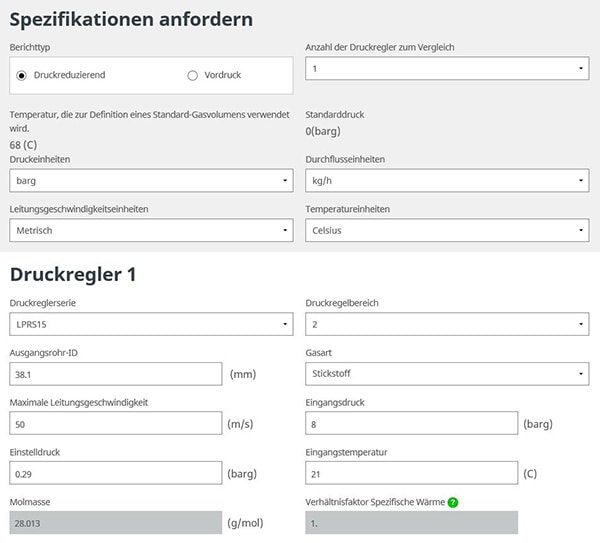
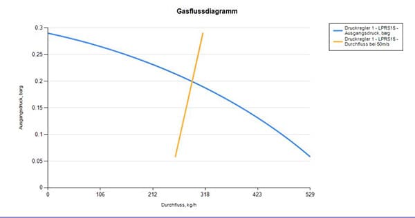
Diagram created from this:
Please note:
The flow diagram does not show the lock-up pressure for an application. However, the shut-off pressure is factory tested and should not exceed 10% of the maximum control pressure of a pressure regulator configuration. This should be taken into account in the performance of a pressure regulator for each application. To learn more about pressure regulator performance, please refer to the Pressure Reducing Regulator Flow Diagram (MS-06-114). To learn more about each regulator series, see the Swagelok RHPS Series Regulators catalog (MS-02-430).
Disclaimer
The flow characteristics of the regulators in this report are created from equations used in Swagelok product specifications, basic fluid properties, and stress theory to match product performance. These calculations have been made to take into account specific conditions and should not be used outside these conditions. This information is intended to help in the selection of the controller, but it cannot duplicate the variety of current operating conditions.
Secure product selection
When selecting products, the entire system design must be taken into account to ensure safe, trouble-free operation. The system designer and the user are responsible for function, material compatibility, appropriate performance data and limits of use, as well as for proper handling, operation and maintenance.